Description
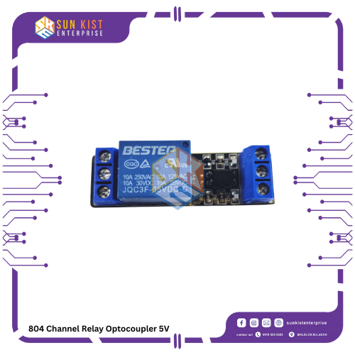
A “5V Channel Relay Module with Optocoupler” is an electronic module used for controlling high-power electrical devices or loads using low-voltage control signals, often from microcontrollers like Arduino or Raspberry Pi. The inclusion of optocouplers in the design helps isolate the low-voltage control circuit from the higher-voltage load circuit for safety and reliability. Here are the key features and components of such a relay module:
1. **Relay:** The module typically includes one or more relays, each capable of switching high-voltage and high-current loads (e.g., appliances, lights, motors). The relay has a set of common, normally open (NO), and normally closed (NC) contacts.
2. **5V Control Voltage:** These relay modules are designed to be controlled with a 5V control voltage. This low voltage is compatible with many microcontrollers, such as Arduino or Raspberry Pi.
3. **Optocoupler:** An optocoupler, also known as an optoisolator, is used to electrically isolate the control circuit from the load circuit. It consists of an LED (light-emitting diode) on the control side and a photosensitive transistor on the load side. When the LED is energized, it activates the transistor, allowing current to flow through the relay coil, which, in turn, closes or opens the relay contacts.
4. **Relay Status LEDs:** Most relay modules include status LEDs to indicate whether the relay is currently activated or deactivated. This visual feedback can be helpful for debugging and monitoring the status of the controlled devices.
5. **Screw Terminals:** The module often has screw terminals for easy connection of control signals and the load circuit. It typically includes terminals for the 5V control signal, ground (GND), and the common (COM), normally open (NO), and normally closed (NC) contacts.
6. **Protection Diode:** Some relay modules have a flyback diode (also called a protection diode) across the relay coil. This diode helps protect the control circuit from voltage spikes that occur when the relay coil is de-energized, as it can generate a reverse voltage.
7. **Applications:** These relay modules are commonly used in home automation projects, robotics, industrial automation, and various applications where you need to control electrical appliances or devices remotely or based on specific conditions.
8. **Driver Circuitry:** The relay module may include driver circuitry to ensure that the relay is properly energized when the control signal is applied. It may also have transistor or IC-based switching circuits for reliable operation.
9. **Current and Voltage Ratings:** The module’s specifications should be checked to ensure it can handle the voltage and current requirements of your specific load.
When using a 5V Channel Relay Module with Optocoupler, you’ll connect your low-voltage control signals (e.g., from your microcontroller) to the module’s input, and then the module will switch the higher-voltage load circuit on and off based on these signals. Care should be taken when working with higher voltages and currents, and proper electrical safety precautions should be observed. Additionally, be sure to consult the datasheet and documentation provided with the specific relay module for proper usage instructions.


Reviews
There are no reviews yet.